DAPHNE YISHUN ZHOU
Crane Project
Spring 2018
Yutian Cai, Pinxu Ren, Yishun Zhou

Side View
A - Lifting Arm
B - Servo Motor
C - Counterweight
D - Supporting Arm
E - Clamped Base

Clamped Base
Design Challenge

The objective of this project is to design and build a mechanism that is powered by a standard servomotor, which will lift a cylindrical weight. The mechanism is to be clamped in a given position (shown on the left) while the other end lifts a weight that slides along a vertical post. Between the clamping area for the base of your design and the post holding the weight sits an obstacle. The mechanism may not touch the obstacle or any other surface besides the base and the sliding weight. The structure must weigh no more than 20.0 oz, and it must lift the sliding weight by at least 2”.
The way we approached this objective was to design a crane structure with a lever arm attached with the servo motor on the crane, thus lifting the cylindrical weight by a counterweight and the moment provided by the motor.
Theoretical Analysis

Theoretical Servo Torque Calculation:
T1 = w1(d2 + d3) = (5.0)(5.5 + 1.0) = 32.5 oz*in
T2 = w2(d2/2) = (0.5)(5.5/2) = 1.375 oz*in
Tm = 57 oz*in
Ttot = T1 + T2 + T3 = 32.5 + 1.375 + 57 = 90.875 oz*in
Assumptions
-
The density of the members and the block is uniform so that the center of gravity lies at half of its total length
-
The weights of the members and the block lie on the same plane
-
The motor connection coincides exactly with the center of gravity of the lifting arm
-
The connections between members are end to end, so that the position of members’ center of gravity is not affected
Theoretical Lift Distance Calculation:
h = d1 ÷ cos( π/4 ) = 2.875√2 = 4.07 in

Feature and Details


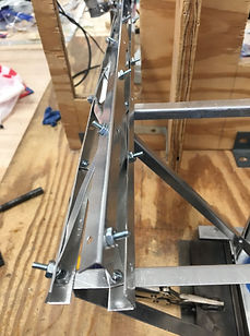

We used a triangular structure in our design as an important element to increase inertia and ensure stability. As can be seen from the images on the left, the base was composed of triangles formed by diagonal crossings of steel bars. And the supporting arm was also constructed so that it has a triangular cross-section.
We iterated the design by keeping the base and extending the supporting arm. This improvement is better explained in the next section.

Improvement


Design 1: Long Lever Arm
Design 2: Short Lever Arm
In our first design, our lifting mechanism consists of a really long counterweighted lever arm that has a counterweight about 40 cm from the servo rotation center. Because we did not manage the materials we need to use carefully, the place we position our servo is a little bit far to the pole we want to lift the weight on, thus in order to reach the weight and lift it up, we need to make a long arm to apply lifting force on the weight, which makes the moment provided by the weight to be so large, that we need a really long arm to counterweight that could be able to actuate the servo motor.
At first, our counterweight lever is straight, then we found the issue that the counterweight put at the end of the lever could be blocked by the ground, so that makes the lifting weight cannot be able to reach the desired height. Thus, we changed the lever arm to “L” shape, which bends the counterweight upwards and we hope this will save the space.
Then we discovered the issue that we cannot make such a structure that could be able to not rotate by the torque applied by the “L” shaped lever, the lever will finally rotate to the side and will hit the crane or hit the ground. We added weight and shortened the counterweight arm to pass the first checkpoint, and our crane still touches the ground.
After the first check, we have some other materials that we could use, so in our final design, we elongated the arm of our crane, so that the servo is closer to the pole, and we could apply a shorter counterweight arm. When the servo is engaged, the lever arm swings through its range of motion, from 45 degrees below the horizontal to 45 degrees above, which caused the loop we made from aluminum at the far end to drag the weight and lift it 2 inches up. By reducing the torsional moment produced by the weight, we also reduced the weight of our crane.